FOB Price
Get Latest Price7 USD / Piece
|1 Unit Minimum Order
Country:
China
Model No:
04K-SD/SP-NO-AL
FOB Price:
7 USD / Piece Get Latest Price
Place of Origin:
China
Price for Minimum Order:
7 per Piece
Minimum Order Quantity:
1 Unit
Packaging Detail:
Inside package is sponge foam , outside package is carton
Delivery Time:
within 3 days after payment
Supplying Ability:
1000000 Unit per Month
Payment Type:
T/T, Western Union, Money Gram, PayPal
Product Group :
Contact Person Ms. Solin
xihefang, Guangzhou, Guangdong
Handbook of Application
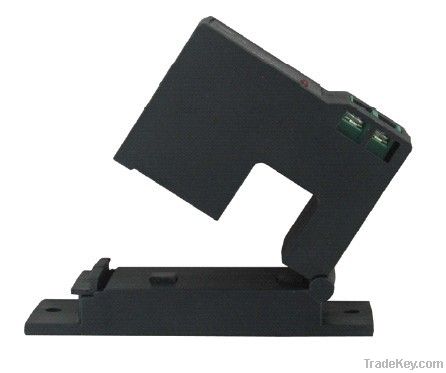
Current Switches
The Series are intended to monitor the operating status of fans, pumps, and motors. These self-powered switches can be hung or tied directly to cables or wires. For use on existing installation, split core models can be installed without disconnecting cables. LED indicators provide a visual confirmation that the current is passing through the core. Both fixed and adjustable set points are available. The adjustable models easily adjust the set point with a potentiometer.
Operating Instructions
The Series of Current Switches offer an to equipment under normal operating conditions. Where failure or malfunction of the current switch could result in personal injury or property damage to the controlled equipment or other property, additional precautions, must be designed into the control system. Incorporate and maintain other devices such as supervisory or alarm systems or safety or limit controls intended to warn of , or protect against, failure or malfunction of the Series.
Risk of Shock
Disconnect power supply before making electrical connections. Contact with components carrying hazardous voltage can cause electrical shock and may result in severe personal injury or death.
Installation
Mounting
For split core devices: open the core using the release tab. Snap the core closed around the power conductor cable. Make sure that the core release tab is locked in its original position.
Specifications
Amperage Range: 0~**0A AC
Maximum Switch Rating:
For fixed set point models: 0.3A at **5V AC/DC
For adjustable set point models: 1A at **0V AC
Output: Normally open.
Power Requirements: None, Self-powered.
Operating Temperature: **0~*0 centigrade degrees
Operating Humidity: 0~*5%(non-condensing).
Frequency:*0~**0Hz
Enclosure Rating: UL,*4 V-O flammability rated, ABS plastic housing.
Approvals: UL & cUL CE & Rohs
LED Indicators
Green LED: indicates that current is passing through the core, but the set point has not been reached and the contacts are open.
Red LED: indicates that the set point has been reached and the contacts are now closed.
Increasing Measured Current
If measured current is too low to be detected:
Wrap the conductor (wire) through the sensing hole and around the FCS body to produce multiple turns to increase the measured current. Use the below equation to determine how many wraps are necessary: Measured current=Actual Current × the Number of Turns
Notice:Failure to derate the current capacity could cause damage to the sensors when using multiple turns to increase the measured current. Use the following formula to determine the new maximum current: Current=**0A/4=*0A
Set Point Calibration (for adjustable models only)
The output switch of all devices is open. When the monitored current exceeds the trip value as set by the set point calibration, the switch will close. The red LED light will indicate that this change has occurred.
The Series of current switches are factory set at the minimum switch point (adjustment fully clockwise)
To Increase the set point:
Use the potentiometer to adjust the range:
Notice: The adjustment should be turned slightly clockwise past a certain point to ensure normal line current variations do not cause false conditions.
LED Indicators
Green LED: indicates that current is passing through the core, but the set point has not been reached and the contacts are open.
Red LED: indicates that the set point has been reached and the
contacts are now closed.
| Country: | China |
| Model No: | 04K-SD/SP-NO-AL |
| FOB Price: | 7 / Piece Get Latest Price |
| Place of Origin: | China |
| Price for Minimum Order: | 7 per Piece |
| Minimum Order Quantity: | 1 Unit |
| Packaging Detail: | Inside package is sponge foam , outside package is carton |
| Delivery Time: | within 3 days after payment |
| Supplying Ability: | 1000000 Unit per Month |
| Payment Type: | T/T, Western Union, Money Gram, PayPal |
| Product Group : | current switch |


